MBTA Display
In this project, we make a PCB map of the Boston MBTA Subway (aka “the T”) that shows the real-time positions of all the subway cars.
The development of the MBTA Display was sponsored by MIT ProjX and was completed with the help of Nathan Huffman.
This project is similar to the TrainTrackr project! I knew this going in, so even though this is a ground-up implementation, all credit for the idea goes to the TrainTrackr team.
This project is conceptually pretty simple: use a wifi-enable microcontroller like an ESP32 to fetch the car locations using the MBTA API and then turn on some LEDs. However, the devil is definitely in the details with this one!
- At the time of this project, there were 120 T stops that needed to be represented. Driving 120 LEDs requires some thought!
- The MBTA API returns data in JSON format. Does the ESP32 even have enough memory to hold the response? Only one way to find out!
Component Selection Link to heading
Microcontroller Link to heading
In the space of small, wifi-enabled boards, maybe the two most popular options are the ESP32 and the Raspberry Pi Zero. The ESP32 is much cheaper and mounts more easily on the PCB. As long as it has enough RAM to hold the JSON response from the MBTA API, it should be sufficient.
LEDs and a Driver Link to heading
There are a lot of T stops, each of which needed a LED indicator. At the time of this project, this was the count of the stops I needed:
- Blue Line: 12
- Red Line: 22
- Green Line: 66
- Orange Line: 20
- Total: 120
With 120 LEDs total, there are a few things to consider:
- Size: each LED should proably be no bigger than 1 or 2 mm on each side.
- Resistors: avoiding a separate current-limiting resistor will significantly reduce the number of components and the visual clutter of the board.
- Cost: small cost savings per LED will scale. Additionally, minimizing the PCB size will help reduce the cost too.
Neopixels Link to heading
One solution I considered was something like the Adafruit 1515 NeoPixel. This is their smallest NeoPixel LED, coming in at 1.5mm on each side. This solution brings numerous advantages:
- They have built-in constant-current drives, eliminating the need for current-limiting resistors.
- They are RGB-enabled, so the same part could be used for each stop regardless of the line color, allowing for BOM consolidation.
- They have shift registers built in! I could control the entire set of LEDs using just two pins and no external drivers! This would also greatly simplify the PCB routing.
There are downsides as well though:
- From Adafruit, they cost $3.95 for a pack of 10 ($3.56 at quantity), bringing the cost to $42.72 per board1.
- They come in square packages. Unlike rectangular SMT LEDs, they cannot be rotated to pack more closely. I also just found the square package to be less aesthetically pleasing, and since this board is a display piece, that was important to me.
For these reasons, I opted to find a different solution.
SMT LEDs Link to heading
The “boring” solution is to just use your regular SMT LED. Some quick estimation suggests that 0603 LEDs (1.55 mm x 0.85 mm) are about the right size.
- On LCSC, each one is about 1.5 cents, bringing the LED cost to a ridiculously low $1.80.
- These tiny LEDs can be packed very tightly. When placed end-to-end, they even look like a row of subway cars!
The major downside of the 0603 LEDs is that they will need an external driver. This driver must be able to multiplex over all the LEDs to save pins and must also have a constant current source to avoid current-limiting resistors and to ensure that LEDs of different colors are equally bright.
I found the MAX7219 which was designed to drive an 8-digit seven-segment display (with decimal points). The data is piped in through a single wire, and the chips can be daisy-chained. Since each controller can control 64 LEDs, I needed two of them. Each part is $2.45 on LCSC for a total of $4.902.
As a final bit of housekeeping, the ESP32 development board uses 3.3 V logic while the MAX7219 requires a minimum logic high voltage of 3.5 V. While this might have been close enough, it was not worth taking the chance. I found the TXB0108PWR voltage level shifter to do the translation. This chip is definitely overkill, but it was cheap enough to be worth avoiding thinking about clever solutions.
Circuit Design and Board Layout Link to heading
I was planning to use JLCPCB to assemble the boards, so I opted to use their EDA software (EasyEDA). The schematic came together fairly quickly, although, as a dramatic forshadowing, you may notice that the revision number is at 0.2 in the image below. It was also around this time that I realized that routing a matrix on a 2D board was going to be a nightmare.
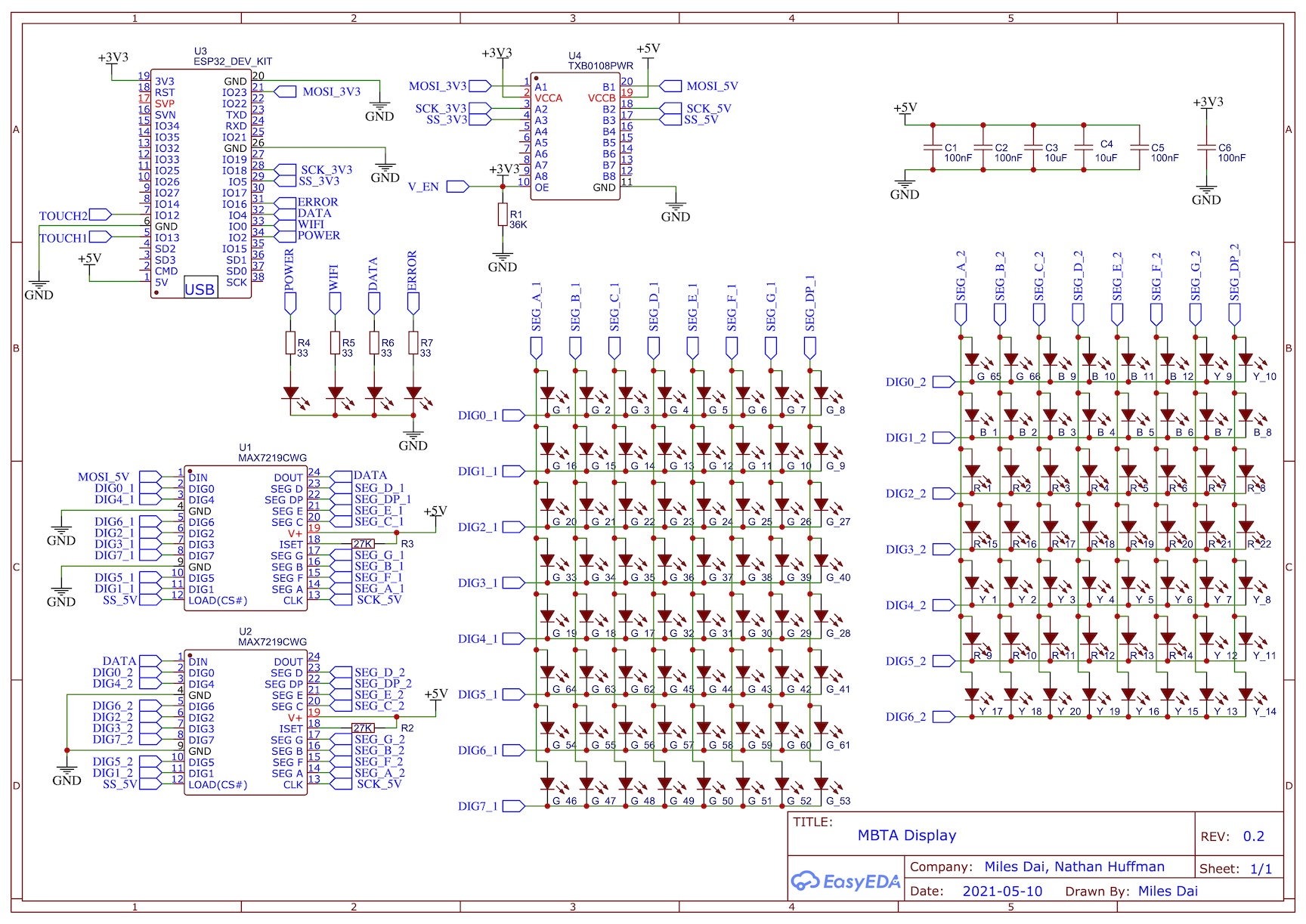
MBTA Display circuit schematic
Laying out the components on this board was less complicated than I had expected. The positions of the LEDs are already determined since they coincide with T stop locations. I took a map of the T, removed all elements except the tracks, and then imported the image onto the silkscreen layer. From there, I fiddled with the positions of the stops until they looked about right.
One thing I realized after doing the layout was that it would have been smarter to arrange the LEDs on the schematic based on their physical location on the board. When I was drawing out the circuit, I had organized all the LEDs by color since it was easier for bookkeeping. However, by the very nature of the subway, LEDs of the same color should be distributed across the map, making routing challenging. Instead, the LEDs should be assigned to the drivers spatially, and the messy LED mapping can just be handled in software. I was saved from my oversight because the Green Line is clustered on the left half of the board anyway, so my naive assignment had naturally clustered most of the Green Line.
Ultimately, with enough persistance, I arrived at the following routing. I am no PCB designer, but having finished the design late at night, I was just glad to have the DRC pass without too many egregious routes. I also added two exposed touch pads in case I ever wanted to experiment with the ESP32’s cap touch sensing abilities. Retrospectively, having a ground plane as the second layer probably would have helped tremendously with the routing.
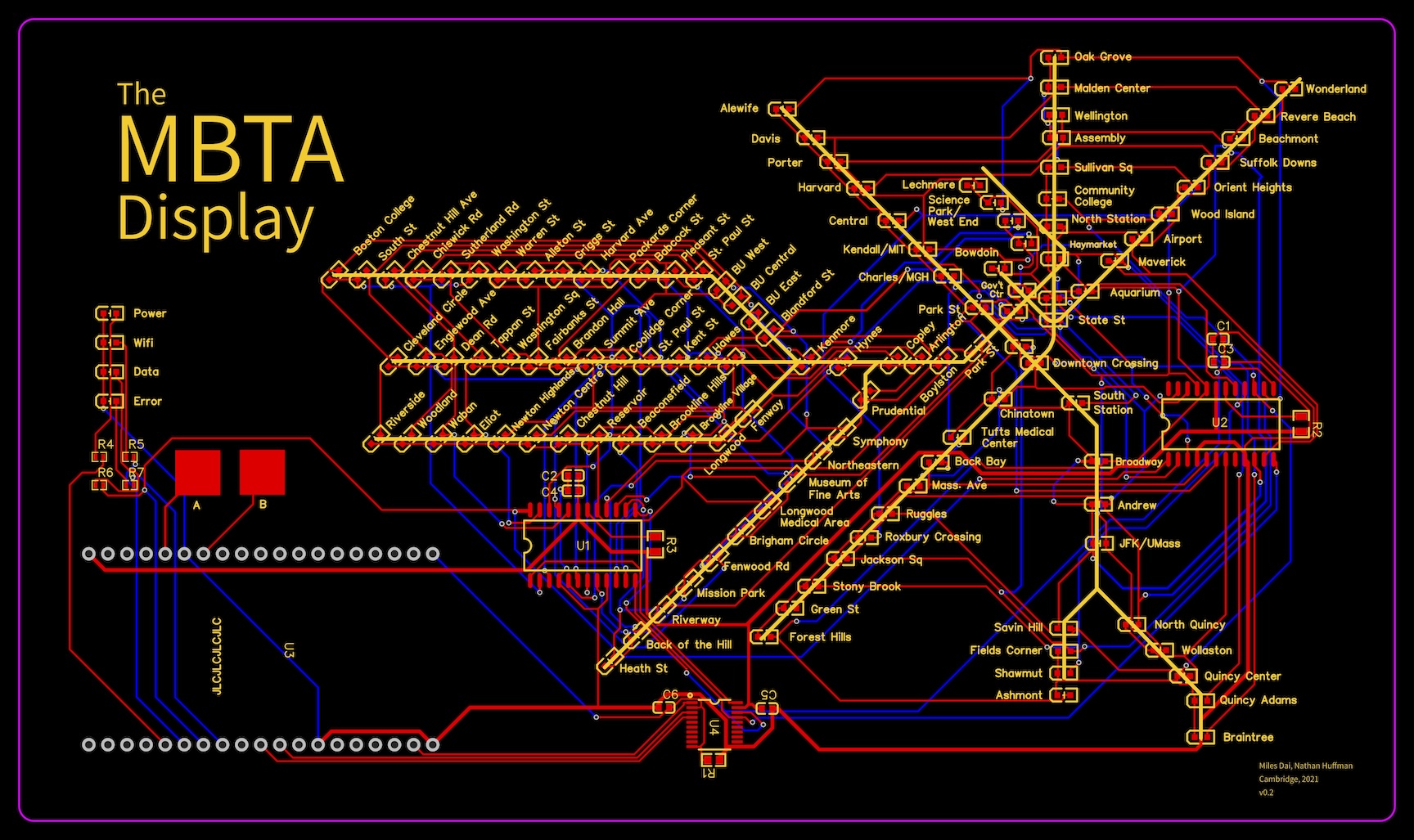
Routing diagram
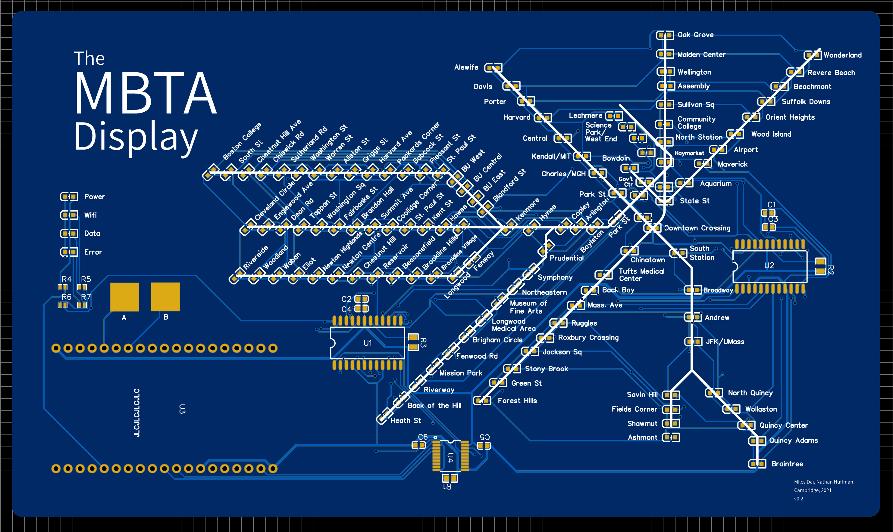
2D rendering
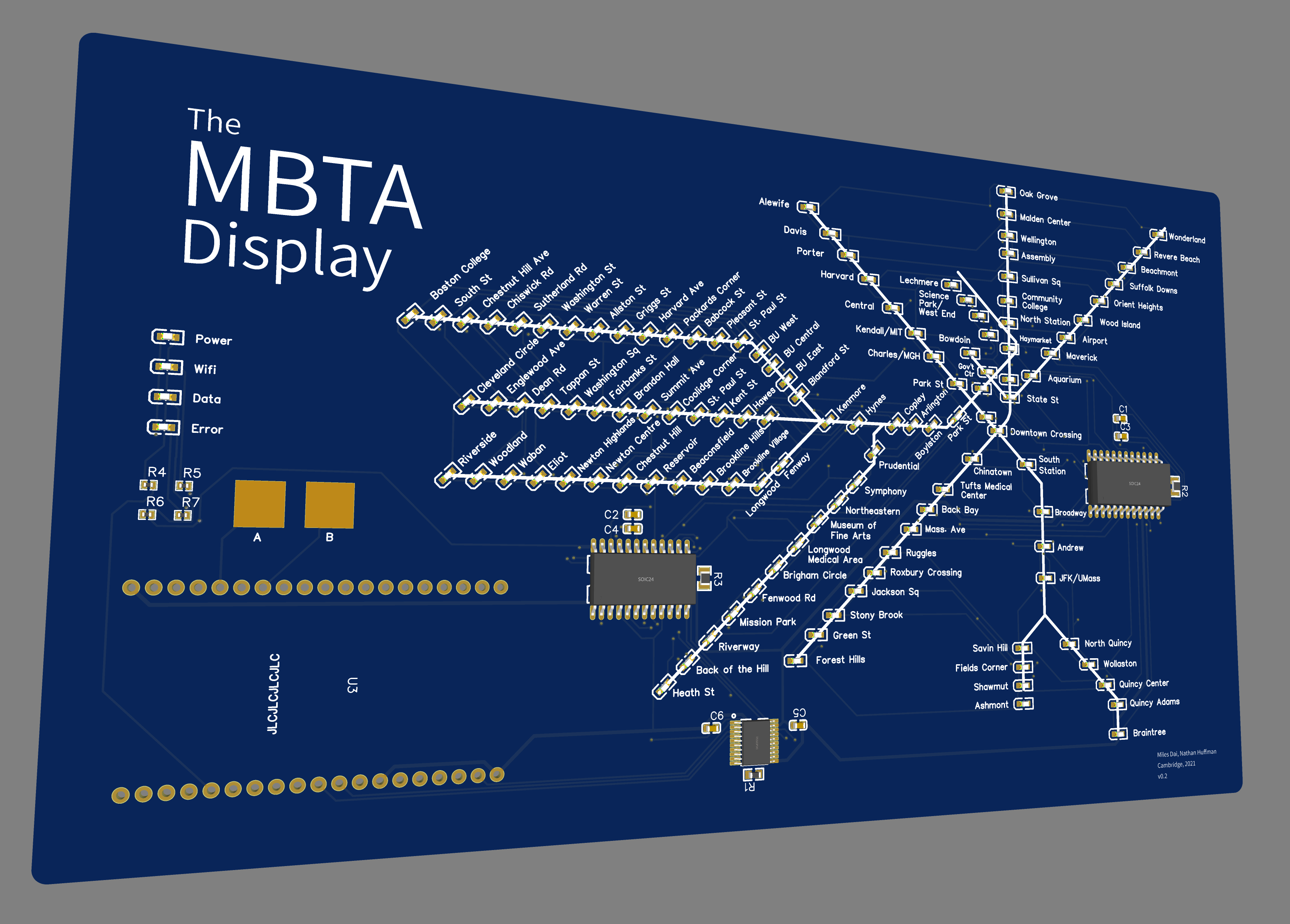
3D rendering
With the routing done, I generated ordered the board from JLCPCB. The ordering process was surprisingly easy. They really have done a great job with the integration between EasyEDA, JLCPCB, and LCSC.
Software Link to heading
The train data comes from the MBTA V3 API which provides data following the General Transit Feed Specification (GTFS) as well as some MBTA-specific data. The API is well-documented and fairly intuitive. In particular, we were able to find all relevant data using the following call (click the link to see the JSON response):
https://api-v3.mbta.com/vehicles?filter[route_type]=0,1&fields[vehicle]=current_status,direction_id
With the data in hand, the rest of the firmware largely consisted of gluing together several libraries. One notable feature we wanted was to perform all the processing onboard the ESP32 instead of hosting a separate cloud server for pre-processing data. To accomplish this, we used a streaming JSON parser to avoid storing the entire response in memory.
The following libraries performed the majority of the work:
- Wifi configuration: WiFiManager
- HTTP request: HTTPClient library (from Espressif’s Arduino-ESP32 library collection)
- JSON parsing: json-streaming-parser2
- LED display: LedController
Final Product Link to heading
After assembling the board and installing the ESP32, I found two errors in the board, leading to some revisions:
- I forgot to pull the output enable (OE) pin high on the TXB0108PWR level shifter chip.
In the schematic, I had originally tied this to a net named
V_EN, but I never pulled the net high to 3.3 V. This prevented the ESP32 from communicating with the LED drivers, so none of the LEDs lit up. A quick bodge wire (visible in the final board below) fixed this. - I accidentally named two different nets
DATA: the data output of the first LED driver and the signal from the ESP32 to the Data LED. This was fixed by cutting the trace to disconnect the two signals.
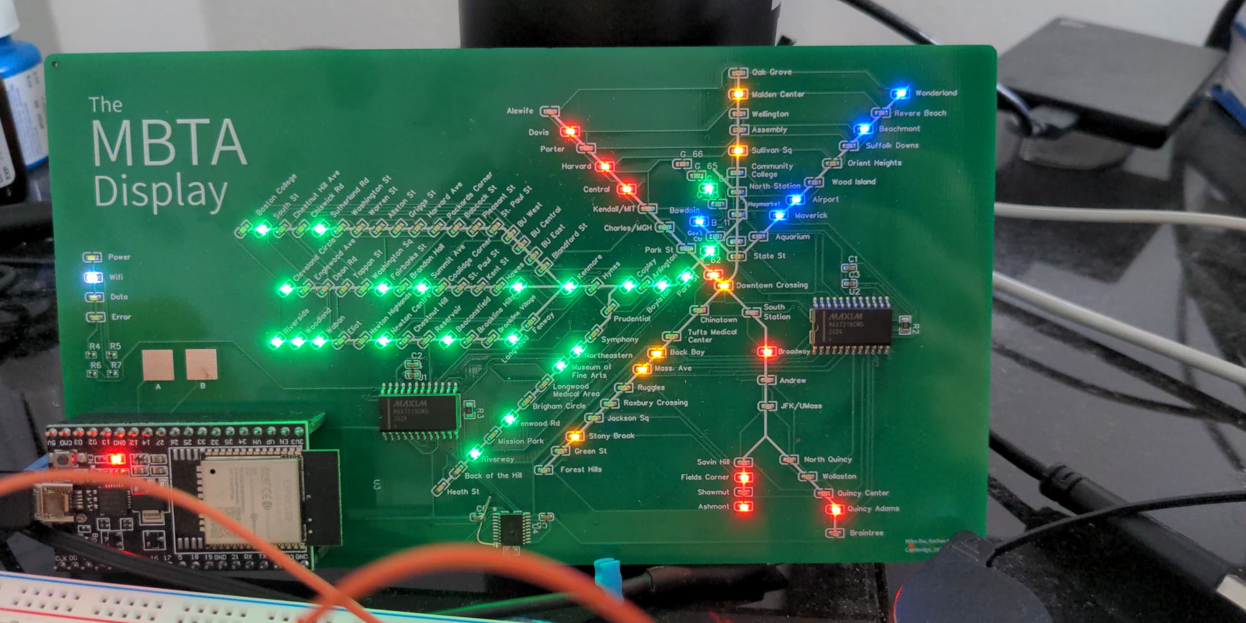
With these two fixes done, the board was complete!
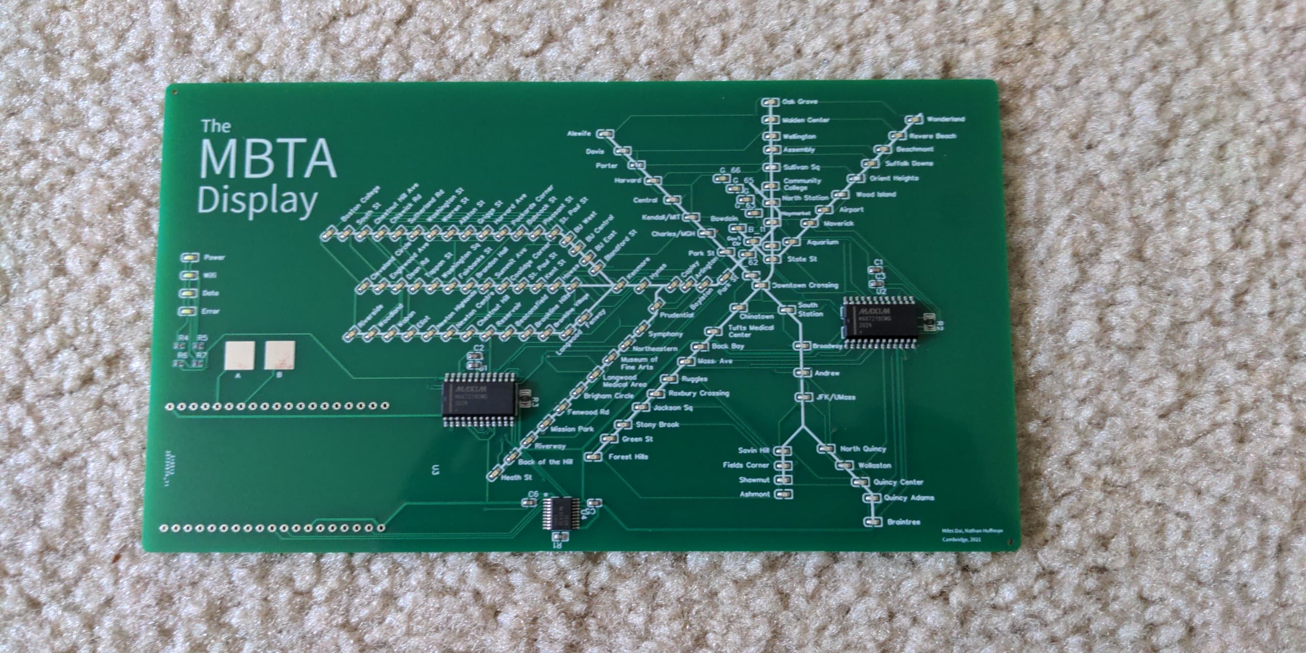
SMT assembly results
Final board!
Interestingly, while writing up this post, I did a quick search on LCSC for SK6805 (the actual NeoPixel part number) and found that they were being sold for about 8 cents each. This gives a total of $9.60 for each board. Perhaps if I were doing this again today, the NeoPixels would be a stronger contender, but nonetheless, they do have some other flaws as discussed above. ↩︎
Looking through the search results now, it appears that there is a Chinese clone of this part that sells for $0.79 under the name Xinluda (XL7219). ↩︎